
Port Basics
When tuning a ported enclosure, there are two widely used methods implemented. These two methods involve the use of a port, generally made from a simple piece of PVC pipe, or a duct (sometimes called a slot port), which is normally constructed out of the same material the box is made of (normally wood).
Before we can discuss how to make a port, it is important to know what factors affect the tuning frequency of the enclosure. It is a common misconception that the tuning frequency (Fb) is a function of port volume when, in fact, it is actually a function of the port's cross-sectional area and its length as given by the formula:
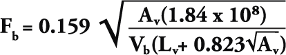
Where Av is the cross-sectional area of the port (in square inches),
Lv is the length of the port (in inches) and
Vb is the enlcosure's net volume (in cubic inches).
Notice that the volume of the port does not come into play. It is also interesting to note that contrary to what one might think, the bigger the diameter of port you use (bigger Av), the longer the port has to be (assuming box volume and tuning frequency are constant).
Round Ports
Port LengthRound ports are really simple to execute since most loudspeaker manufacturers will specify a diameter and length of port for you to use in your particular design. Just remember that the port diameter that all manufacturers speak of is the port's internal diameter, not the outside diameter.
The length specified is simply the length of the port from end to end, not just the length of the port inside the enclosure.
When using round or slot ports, it is important to use either a file or a piece of sandpaper and round off the inside edges of both ends of the port to minimize the likelihood that your port would make whistling noises (caused by air moving rapidly over a sharp edge, like that found on a whistle or a 1978 Cadillac doing 70mph).
Slot / Duct Ports
Ducts are often used when a particular alignment calls for an outrageously long port to be squeezed in a very tiny enclosure due to a very low tuning. This scenario is commonly encountered when constructing ported enclosures for long excursion drivers.
Designing and implementing a duct in your own project is really not as hard as it may seem at first. However, there are a few guidelines you must follow if you are to experience any degree of success utilizing this porting technique.
Below is a perspective view of a typical duct port along with a few helpful tips on how to get the best results from your duct.
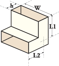
Av The cross-sectional area (found by multiplying h and W) should be the same as that prescribed for a round port. For example, if our design calls for a 4" diameter port, our duct's cross-sectional area should be 12.57 square inches.
W/h The ratio of W to h should not be any more than 9 to 1 to prevent tuning shifts introduced by excessive friction between the rapidly moving air and the port's surface. It should be noted that this is not a hard-and-fast rule, merely a rule of thumb to help you prevent a mis-tuning.
In short, keep the port as square as aesthetically and physically possible.
Lv (phys) The physical length of the port is measured down the dead center of the port from end to end. In the picture above, this would correspond to L1 + L2, but the physical length of the port isn't really what is important; it's the effective length of the port (with end correction) that is important.
Lv (eff)
The effective length of the port is found by adding an end correction factor. An end correction factor is necessary because, more often than not, one wall of the port is also one wall of the enclosure. This wall extends beyond the end of the port, thus effectively adding length to the port (remember, the driver can't "see" the length of the port, it can only go by what it "feels" is going on).
End Correction Factor
Calculating end factor may sound like it would be more trouble than it's worth, but it's actually quite simple. To calculate end correction factor, simply add one-half of h to the physical length you calculated above (L1 + L2).
Multiple Ports
There are two widely used methods for calculating multiple ports for a single chamber. Only one method is correct, but, unfortunately, it is the least commonly used.
The first and incorrect method takes its thinking from the original port formula and basically says that if we take two ports and sum their cross-sectional areas, we can just plug this total into the port formula for Av to get our port length. This would sound reasonable, but it can lead to serious mis-tunings in some cases, as we'll see in an example below.
The second and correct way to figure out how long each port should be follows this simple three-step procedure:
Divide the chamber volume by the number of ports you wish to use for that one chamber.
Take the quotient and use that as your Vb (box volume) in the port formula.
Do the number crunching and figure out how long each port should be.
Example:
Let's take an arbitrary box volume of 2.5 cubic feet that we want to tune to 25 Hz with a 4" diameter port. If we plug and chug with that big hairy formula (or let our favorite software package churn out the numbers), we'll find that Lv = 18.844 inches.
Now let's decide that we don't want just a single port because it looks boring. Let's put a 2" port in each corner of the box for a total of 4 ports and see what the two methods give us:
Method 1:
Each 2" port has a cross-sectional area of 3.142 square inches, so we multiply that by 4 to get 12.57 square inches. Plugging in 12.57 for Av in the port formula yields Lv = 18.844 inches for each port.
Method 2:
We want to use 4 ports so we divide 2.5 cubic feet by 4 and get .625 cubic feet. Vb now becomes .625 cubic feet. We are using 2 inch diameter ports so Av is 3.142 square inches. Plugging these numbers into the equation leads to Lv = 20.302 inches for each port.
Notice that Method 1 produces the same port length as did our single 4" diameter port, which is to be expected. (After all, we have the same total port cross-sectional area, which this school of thought proclaims is correct!) However, the first method is incorrect because it neglects the frictional losses encountered by using many smaller ports there is a higher port wall surface area to cross-sectional area ratio, which raises the total amount of frictional losses in the ports and, therefore, shifts the tuning!